Component No. 1
Oil Circulation
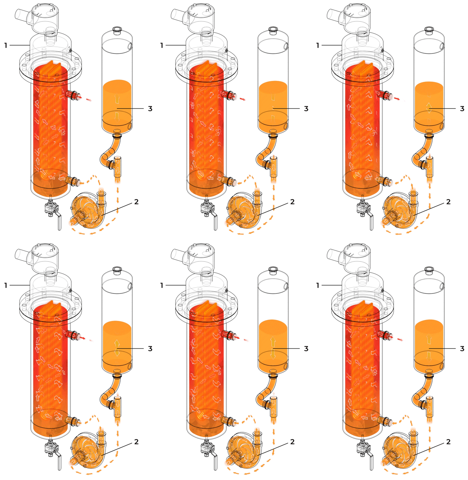
Component No. 1
Oil Circulation
The hot oil system reliably delivers heat to the system in a safe and controllable manner.
- A powerful explosion-proof immersion heater brings the thermal fluid to the target temperature. The thermal fluid temperature is controlled using proportional controllers, ensuring accurate and uniform heat delivery. This system typically operates between 140°C and 160°C.
- A powerful circulation pump, rated for high temperatures, circulates the hot thermal fluid. Rapid thermal fluid circulation is critical to ensure uniform heating, keeping operation nice and smooth.
- The oil expansion tank allows for the expansion and contraction of the thermal fluid.
Component No. 2
Falling Film Evaporator
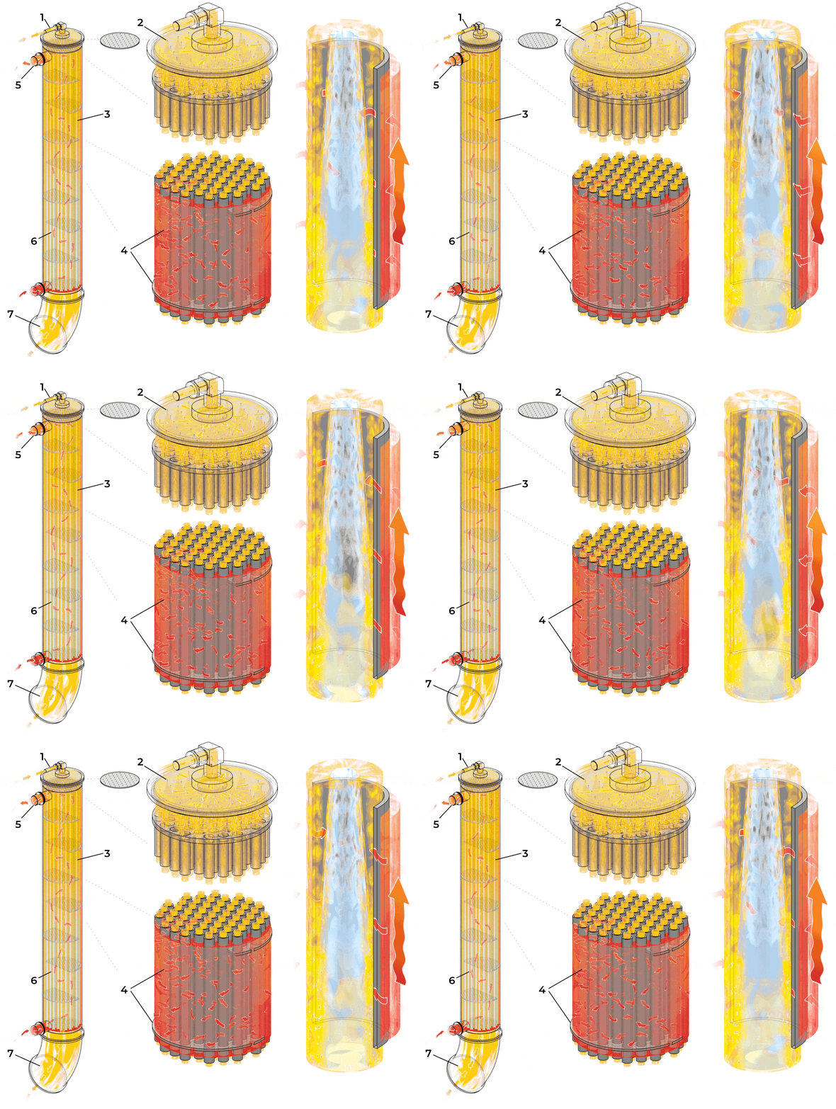
The Falling Film Evaporator provides high-throughput solvent evaporation without degrading or overheating the product.
- The solution enters the top of the falling film and is passed through a dispersion plate.
- The dispersion plate ensures even distribution across the inner surfaces of all evaporator tubes. Uniform distribution of solution is crucial in maximizing evaporator efficiency.
- The solution contacts the evaporator tubes, which are heated by the hot oil system. Once the solution contacts the tubes it is heated to the solvent’s boiling point. This causes the solvent to evaporate, leaving the concentrate behind.
- Baffles in the shell and tube exchanger cause the thermal fluid to spread through the tubes. This minimizes channeling and maximizes heat transfer to the tubes.
- The thermal fluid exits the shell and tube exchanger after having given much of its thermal energy to the now-gaseous solvent.
- As the solvent vapor flows down the tubes it spreads the concentrate along the inside of the tubes, increasing surface area and further increasing the rate of solvent evaporation.
- After the solvent has been evaporated, the purified concentrate drains out of the bottom of the evaporator and runs into the collection vessel.
Component No. 3
Collection Vessel
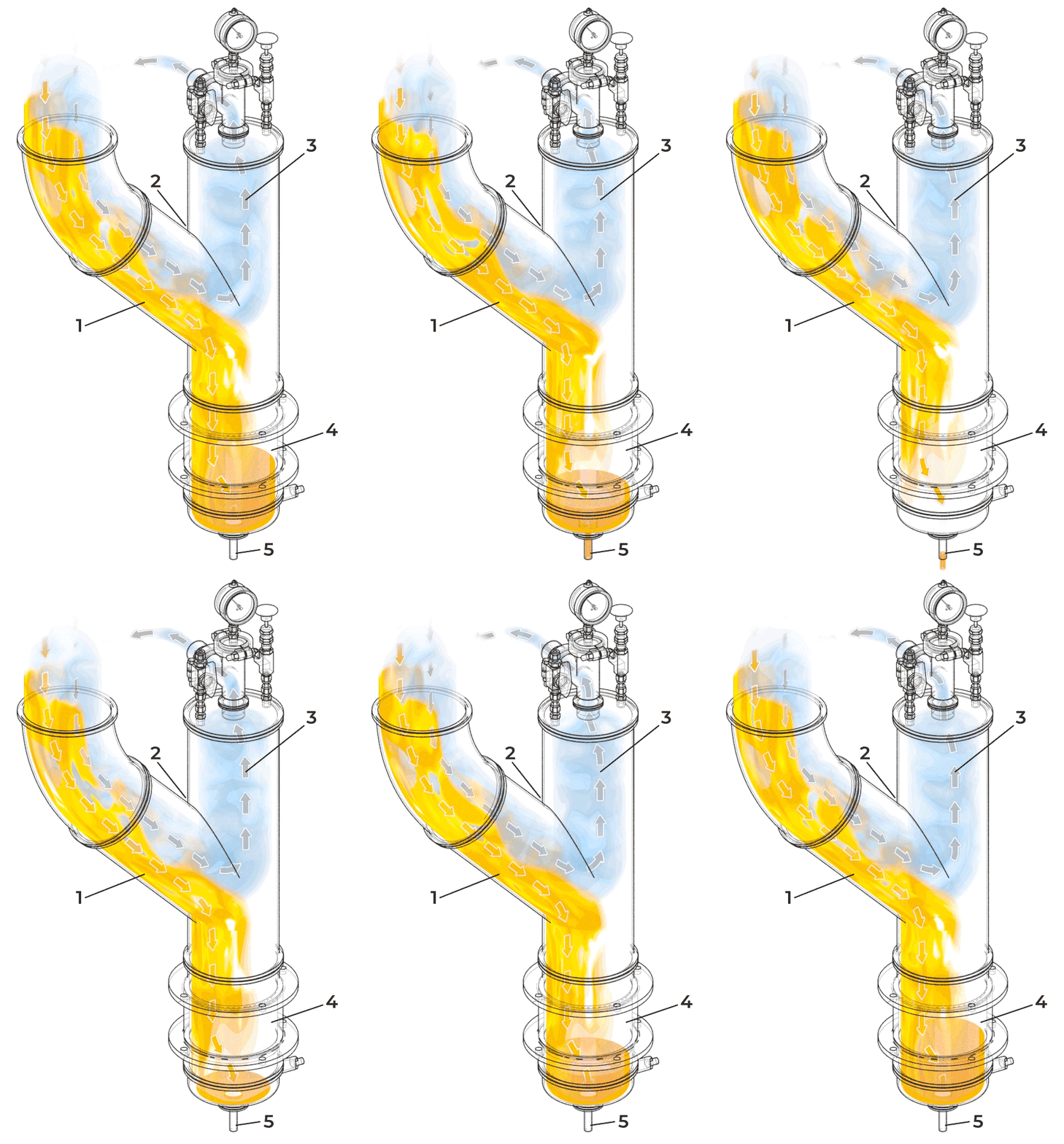
Component No. 3
Collection Vessel
Collection and removal of the concentrated solvent-free product. The collection vessel automatically drains, reducing the need for operator monitoring and input.
- The purified liquid concentrate, now free of solvent, flows from the bottom of the evaporator and accumulates in the collection vessel.
- A wide aperture is used on this vessel in order to avoid constricting gas flow. Constricting the gas flow increases the speed of the molecules, increasing the likelihood of concentrate being carried with the gas into the condenser. This is called carry-over and it is undesirable, as it contaminates the recovered solvent stream.
- The solvent vapor travels past the collection vessel, through the preheating exchanger, and into the condenser to be recovered.
- A full view sight glass allows operators to visually assess the viscosity of concentrates in order to gauge their dryness.
- A level switch monitors the concentrate levels in the collection vessel and activates the automatic drain valve. Concentrates are automatically unloaded, assisted by the 1-5 PSI of system pressure.
Component No. 4
Preheating Plate Exchanger
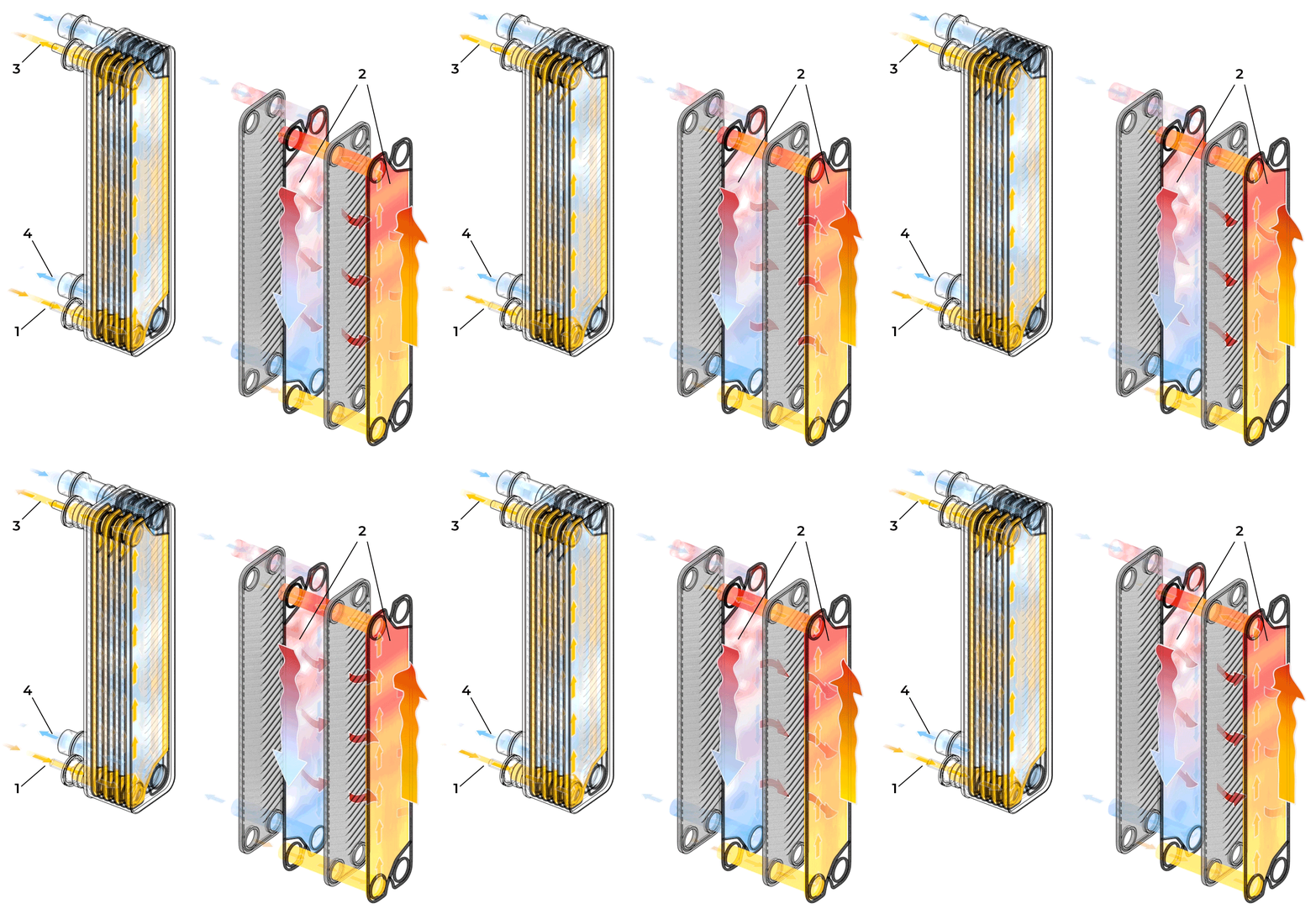
Captures excess heat to increase efficiency and reduce energy requirements for evaporating and condensing.
- On its way to the evaporator, solution first travels through the preheating plate exchanger.
- The exchanger has two separate streams, separated by a series of convoluted plates. The inlet solution travels through one stream, while hot solvent vapor travels through the other. These separate streams exchange their heat through contacting the plates, warming the inlet stream and cooling the vapor stream.
- The now-heated inlet solution continues on to the evaporator, where it will require less energy to reach evaporation temperatures. This exchanger allows the system to handle inlet solution temperatures as low as -60C and actually gains efficiency at cooler inlet temperatures.
- The solvent vapor stream, having given up a lot of its energy to the inlet stream, begins to condense into liquid solvent at this stage. The liquid-vapor mixture carries on to the condenser to finish the job. Removing heat in this exchanger reduces the cooling load on the condenser, increasing overall efficiency.
Component No. 5
Diffusion Condenser
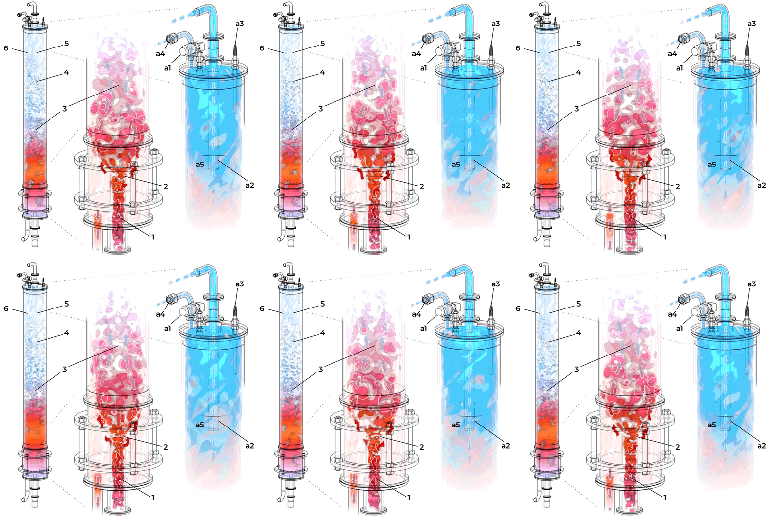
Efficient condensation without chillers saves both money and energy.
- Solvent vapor is injected into the Diffusion Condenser, which contains a solvent reservoir. This reservoir is constantly recirculated through a heat exchanger in order to maintain its temperature.
- A low pressure zone is created where the solvent vapor enters the condenser. This causes rapid cavitation of the bubbles, which creates greater interaction between the gas and liquid phases, further expediting condensation. The low pressure zone also draws in cold liquid solvent which mixes with the solvent vapor.
- The solvent vapor rapidly condenses as it is mixed with the cool liquid solvent. The high surface area interactions and excellent heat transfer ability between the gas and liquid allow for solvent vapor to be condensed at high temperatures when compared to solid surface condensation.
- As bubbles cavitate, their surface area to volume ratio increases exponentially, resulting in an increased rate of heat dissipation.
- A large channel of liquid solvent ensures that all the solvent vapor is condensed, even while running at high speeds.
- Without the need for low temperatures for condensation, heat can easily be rejected from the liquid using just a radiator and air flow.
Component No. 6
Condenser Flow
Component No. 6
Condenser Flow
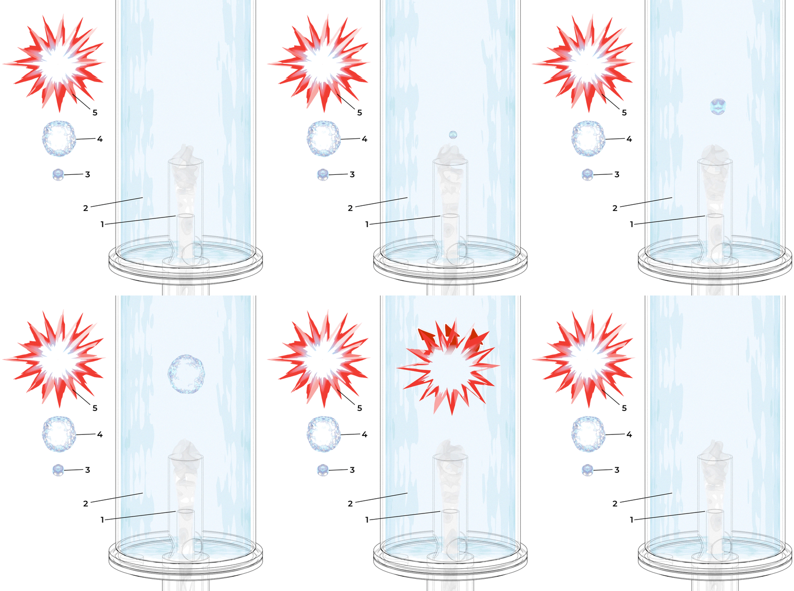
Maximum surface area interactions make our patented Diffusion Condenser more efficient than any on the market.
- Vapor from the evaporator comes in through the nozzle. As the solvent vapor enters the liquid solvent it forms a bubble of superheated vapor.
- Cold liquid flows downwards in the condenser, circulating the cold liquids closer to the sparger while warmer liquid rises up the column.
- The pressure is lower in the condenser so the bubble expands and the vapor molecules hit the walls inside the bubble and dissipate their energy.
- The surface area increases until entirely condensed.
- There is an empty space where the vapor used to be, at near complete vacuum. The liquid accelerates inwards rapidly and “cavitates” making a loud pop.
Component No. 7
Condensing Plate Exchanger
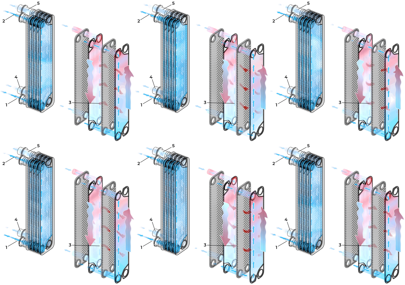
Rejecting heat to a water stream keeps the condenser at the ideal operating temperature.
- Cool water returning from the radiator fills the plate exchanger and removes heat from the warm solvent.
- The warmed water is pumped to the radiator outside where the heat is dissipated.
- Heat passes through the wall of the plate exchanger from the solvent to the water as the fluid temperatures approach equilibrium.
- The cooled solvent goes back to the condenser to help maintain the reservoir temperature.
- Warm solvent from the condenser is pumped through the plate exchanger and dissipates much of its heat.
Component No. 8
Water Circulation
Component No. 8
Water Circulation
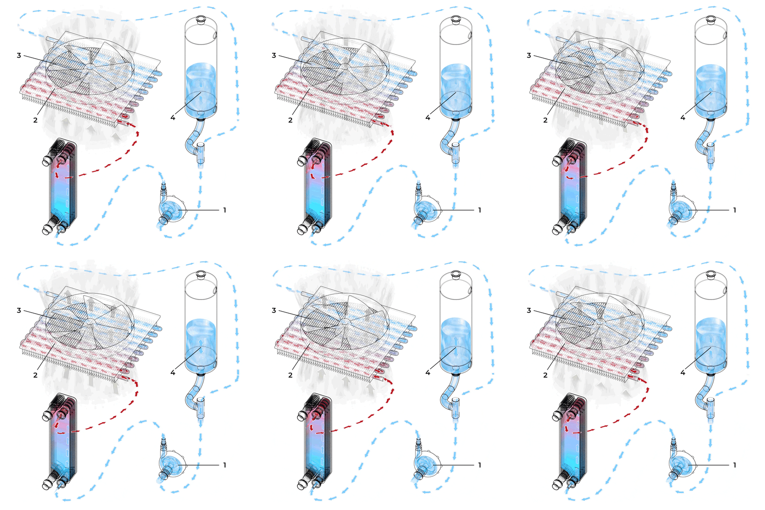
Heat from the condenser is removed to a radiator and blown into the atmosphere. The radiator assembly uses a fraction of the energy required for a chiller.
- A centrifugal pump rapidly and reliably circulates water through the system. Rapid circulation ensures that not only can the cooling system keep up with the high evaporation rate, but it can do so without significant temperature gradients.
- Water is circulated through a dry fluid cooler, which moves air over a rows of small tubes to remove the heat from the water system.
- Radiators are extremely efficient and scalable as they do not involve a refrigerant cycle. Refrigerant cycle based compressor cooling is more suitable for control based situations where bulk heat removal is sacrificed for low temperature operation.
- A buffer tank accounts for thermal expansion and contraction of the water, thus ensuring proper circulation.